What is a MOSFET! This is an obvious question that strikes in the mind of every beginner in the field of electronics. The answer to this question is quite simple but when comes to the point of using a MOSFET in a circuit, it is not that easy.
In this article, we will look into the world of MOSFETs, exploring their different types, practical applications, the gate resistor selection, their role as switches, power dissipation calculations, and the critical aspect of heat sinking, protection circuitry, etc.
Page Contents
- The basic definition of a MOSFET?
- Understanding MOSFET Types
- Types as per Modes
- Important Parameters of MOSFETs
- Gate Resistor Selection: The Art and Science
- MOSFETs as Switches: An In-Depth Look
- Power Dissipation Calculations: A Key Aspect
- Heatsinking: Preventing Overheating
- Practical Application of MOSFET
- Protection Circuitry for MOSFETs
- Conclusion
The basic definition of a MOSFET?
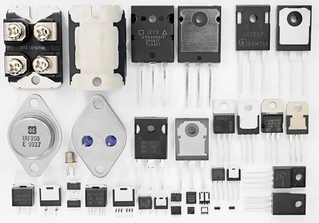
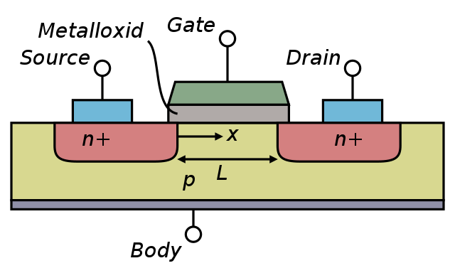
At the core of modern electronics, the MOSFET, or Metal-Oxide-Semiconductor Field-Effect Transistor, is a three-terminal field-effect transistor. Its conductivity is controlled using voltage, unlike the BJT. This voltage-based control makes it suitable for high-speed switching of high-power circuits.
MOSFETs act as electronic switches and amplifiers, allowing precise control of electrical current. These tiny components are commonly used in smartphones, laptops, and a wide range of other electronic devices.
A typical MOSFET has three pins: gate (G), drain (D), and source (S).
Understanding MOSFET Types
N-channel and P-channel MOSFETs are two commonly used types of Metal-Oxide-Semiconductor Field-Effect Transistors, and they exhibit distinct differences in their characteristics and applications.
Here’s an explanation of the differences between N-channel and P-channel MOSFETs:

N-Channel MOSFET:
Conduction: In an N-channel MOSFET, current flows between the drain (D) and the source (S) when a positive voltage is applied to the gate (G) relative to the source. This means that the N-channel MOSFET is typically in the off state, and it becomes conductive when a positive gate-source voltage (VGS) is applied.
Voltage Polarities: N-channel MOSFETs function with positive gate-source voltage (VGS) and require a more positive voltage on the gate compared to the source (VGS > 0) to activate.
Applications: N-channel MOSFETs are widely used due to their superior performance characteristics, including faster switching speeds and lower on-resistance. They find applications in various fields, such as amplifiers, power switches, and motor control.
Voltage Control: N-channel MOSFETs are voltage-controlled devices, meaning they require a voltage signal to regulate the flow of current between the drain and source terminals.
P-Channel MOSFET:
Conduction: In a P-channel MOSFET, current flows between the drain (D) and the source (S) when a negative voltage is applied to the gate (G) relative to the source. P-channel MOSFETs are normally in the off state, and they turn on when a negative gate-source voltage (VGS) is applied.
Voltage Polarities: P-channel MOSFETs function with negative gate-source voltage (VGS) and require a more negative voltage on the gate compared to the source (VGS < 0) to activate.
Applications: P-channel MOSFETs are often used in applications where it is more practical to have a device that is typically in the off state and turns on when a negative gate voltage is applied. They are commonly found in high side series switch applications in power management systems.
Voltage Control: P-channel MOSFETs are also voltage-controlled devices, but the voltage required to turn them on is negative with respect to the source.
Key Differences:
Voltage Polarities: N-channel MOSFETs use positive voltage for gate control (VGS > 0), whereas P-channel MOSFETs use negative voltage for gate control (VGS < 0).
Performance: N-channel MOSFETs generally offer better performance characteristics in terms of on-resistance and switching speed, making them more suitable for high-performance applications.
In summary, N-channel and P-channel MOSFETs have opposite polarities for gate control leading to different applications and use cases. The choice between them depends on the specific needs of a circuit or application.
Types as per Modes
Enhancement-mode and depletion-mode MOSFETs are two distinct types of MOSFETs, each with its unique characteristics and modes of operation.
Here’s an explanation of both types and the key differences between them:
Enhancement-Mode MOSFET:
In an enhancement-mode MOSFET, the device is naturally in an off or non-conductive state when no voltage is applied to its gate terminal. It only becomes conductive and allows current to flow when a positive voltage is applied to the gate terminal. To enhance the conduction of the enhancement-mode MOSFET, a positive gate-source voltage (VGS) is required. Enhancement-mode MOSFETs find common use in applications where precise control over when the transistor conducts current is necessary, such as in digital logic circuits or various switching applications. They are often referred to as normally-off MOSFETs.
Depletion-Mode MOSFET:
Depletion-mode MOSFETs are inherently in an on or conductive state when no voltage is applied to the gate terminal. They require a negative gate-source voltage (VGS) to turn them off and reduce their conductivity. In a depletion-mode MOSFET, the channel is already established, and the transistor conducts without any gate voltage applied. Depletion-mode MOSFETs are used in applications where you want the transistor to be normally conducting and only turn it off when a gate-source voltage is applied. They are sometimes referred to as normally-on MOSFETs.
Key Differences:
Operation State: The primary distinction between the two types lies in their default operational states. Enhancement-mode MOSFETs are naturally off, while depletion-mode MOSFETs are naturally on.
Gate Voltage: Enhancement-mode MOSFETs require a positive gate-source voltage (VGS > 0) to turn the transistor on, while depletion-mode MOSFETs necessitate a negative gate-source voltage (VGS < 0) to turn them off.
Applications: Enhancement-mode MOSFETs are commonly employed in applications where precise control of the transistor’s conductivity is crucial, such as in digital logic and switching circuits. Depletion-mode MOSFETs are used when you want the transistor to be in a conducting state by default and only turn it off when necessary.
Availability: Enhancement-mode MOSFETs are more readily available and widely used in various electronic applications, making them more prevalent than depletion-mode MOSFETs.
In summary, the fundamental difference between enhancement-mode and depletion-mode MOSFETs lies in their default operational states and the gate voltages required to control them. The choice between the two types depends on the specific requirements of the application and the desired behavior of the transistor.
Important Parameters of MOSFETs
Voltage Ratings:
Voltage ratings of the MOSFET is an important parameter. Ensure that the drain-source voltage (VDS) and gate-source voltage (VGS) do not exceed the MOSFET’s specified limits. Exceeding these ratings can damage the MOSFET.
Gate Voltage:
Apply the appropriate gate voltage (VGS) to turn the MOSFET on. For N-channel MOSFETs, a positive voltage with respect to the source (VGS > 0) is needed. P-channel MOSFETs require a negative voltage (VGS < 0).
Gate Resistor Selection: The Art and Science
Selecting the appropriate gate resistor is a critical consideration when working with MOSFETs. It directly impacts switching speed, power dissipation, and electromagnetic interference. To choose the right gate resistor, one must take into account factors such as gate capacitance, drive voltage, and desired switching frequency.
here’s the formula for calculating the gate resistor (RG) for a MOSFET
Gate Resistor (RG) = (T_R / I_G)
Where:
RG is the gate resistor value in ohms (Ω).
T_R is the rise time or fall time of the MOSFET in seconds (s).
I_G is the gate current required for the MOSFET in amperes (A).
Explanation:
- Gate Resistor (RG): This is the resistance value of the resistor you need to connect to the gate terminal of the MOSFET. The gate resistor controls how quickly the gate voltage changes, which, in turn, affects how fast the MOSFET turns on and off. It’s an essential component to prevent excessive gate current, which can potentially harm the MOSFET.
- Rise Time or Fall Time (T_R): Rise time and fall time are measurements of how quickly the voltage at the gate of the MOSFET changes during the switching process. These times are often specified in the MOSFET’s datasheet and are essential for determining the speed of switching.
- Gate Current (I_G): This represents the amount of current required to charge or discharge the gate of the MOSFET. The gate current varies depending on the specific MOSFET and the application and can typically be found in the MOSFET datasheet.
By using this formula, you can calculate the appropriate gate resistor value to achieve the desired switching speed for your MOSFET while ensuring that the gate current remains within safe limits.
MOSFETs as Switches: An In-Depth Look
MOSFETs are frequently configured as switches in electronic circuits. They can control the flow of current by turning on and off based on the voltage applied to their gate terminal. Understanding the principles behind this switching capability is crucial in applications like motor control, Pulse Width Modulation (PWM), and LED lighting.
Using MOSFETs as switches in electronic circuits is a common application. Here are some details on how to effectively use MOSFETs as switches:
Source Connection:
Connect the source pin of the MOSFET to the common ground in your circuit.
Load Connection:
Connect the load (the component you want to control) between the drain and the positive supply voltage (VDD).
Diode Protection (for Inductive Loads):
When switching inductive loads like motors or relays, use a flyback diode (freewheeling diode) in parallel with the load to protect the MOSFET from voltage spikes generated by the inductive kickback.
Snubbers (for Reducing Switching Noise):
In high-frequency applications, you may use snubbers, which are combinations of resistors and capacitors, to reduce switching noise and voltage spikes.
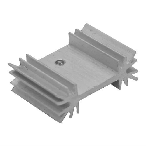
Heat Management:
Consider heat management. If the MOSFET is switching significant power, it can get hot. You may need a heatsink to dissipate the heat efficiently.
Testing:
Before connecting the MOSFET in a critical circuit, test it with the intended load and gate voltage to ensure proper operation.
Control Signals:
Ensure that your control signals (gate voltages) are generated correctly. You can use microcontrollers, digital logic gates, or other circuitry to control the MOSFET.
Power Dissipation Calculations: A Key Aspect
In any electronic system, it’s vital to consider power dissipation in MOSFETs to prevent overheating and ensure their longevity. Calculating power dissipation involves taking into account factors like the drain-source voltage drop and the current passing through the MOSFET. This knowledge is essential for maintaining the MOSFET’s safe operating temperature.
Here’s the formula for power dissipation calculation for a MOSFET:
Power Dissipation (PD) = (VDS * ID)
Where:
⦁ PD is the power dissipation in watts (W).
⦁ VDS is the drain-source voltage in volts (V).
⦁ ID is the drain current in amperes (A).
Explanation:
- Power Dissipation (PD): This is the amount of power that the MOSFET dissipates as heat during its operation. Excessive power dissipation can lead to overheating and potential damage to the MOSFET.
- Drain-Source Voltage (VDS): VDS is the voltage across the drain and source terminals of the MOSFET. It’s the voltage at which the MOSFET is operating in your circuit.
- Drain Current (ID): ID represents the current flowing from the drain to the source of the MOSFET. It’s essential for understanding how much current the MOSFET is handling.
By using this formula, you can calculate the power dissipation to ensure that the MOSFET operates within its safe temperature limits. This information is critical for preventing overheating and maintaining the reliability of the MOSFET in your electronic circuit.
Heatsinking: Preventing Overheating
When MOSFETs dissipate a significant amount of power, they can become hot, potentially causing damage or malfunctions. Heatsinking, which involves using heat sinks or other cooling methods, is employed to dissipate excess heat effectively and maintain the MOSFET’s temperature within safe limits. Parameters such as thermal resistance and maximum junction temperature guide the determination of heatsinking requirements.
I’ll provide the formula for heatsinking calculation:
Heatsinking Requirement (HR) = (T_Jmax – T_Amb) / R_JA
Where:
⦁ HR is the heatsinking requirement in degrees Celsius per watt (°C/W).
⦁ T_Jmax is the maximum junction temperature of the MOSFET in degrees Celsius (°C).
⦁ T_Amb is the ambient temperature in degrees Celsius (°C).
⦁ R_JA is the thermal resistance from the junction to ambient in degrees Celsius per watt (°C/W).
Practical Application of MOSFET
By understanding the different types of MOSFETs, their applications, the significance of gate resistor selection, the role of MOSFETs as switches, power dissipation calculations, and the importance of heatsinking, you can harness the full potential of these versatile components in your electronic projects. This comprehensive knowledge allows you to design and build electronic circuits with improved efficiency and reliability.
MOSFETs (Metal-Oxide-Semiconductor Field-Effect Transistors) are versatile semiconductor devices used in various applications across different industries. Here are some common applications of MOSFETs:
Power Amplification:
MOSFETs are used in audio amplifiers to amplify low-power audio signals, making them suitable for driving speakers and headphones.
Switching Applications:
MOSFETs are employed as electronic switches in a wide range of applications, from digital logic circuits in microprocessors to power switches in power supplies, motor control, and LED lighting.
Motor Control:
In motor control applications, MOSFETs are used to drive and control the speed and direction of electric motors, making them essential in everything from electric vehicles to industrial machinery.
Voltage Regulation:
MOSFETs are used in voltage regulation circuits, such as voltage regulators and power management systems in electronic devices, to ensure a stable supply of power to components.
Pulse Width Modulation (PWM):
MOSFETs are key components in PWM controllers used for controlling the duty cycle and thus the average power delivered to loads like motors, LED dimming, and power inverters.
DC-DC Converters:
In DC-DC converters, MOSFETs are used to efficiently convert one voltage level to another, making them indispensable in power supplies for various applications.
Solar Power Inverters:
In solar power systems, MOSFETs are used in inverters to convert DC power generated by solar panels into AC power for use in homes and businesses.
RF Amplification:
MOSFETs can be used as RF (Radio Frequency) amplifiers in applications such as wireless communication systems, where they amplify high-frequency signals.
Low-Noise Amplifiers (LNAs):
In applications like satellite communication, MOSFETs are used as LNAs to amplify weak signals with minimal added noise.
High-Frequency Switching:
In high-frequency applications, MOSFETs play a critical role in switching signals, as seen in RF switches and mixers in communication devices.
Light Emitting Diode (LED) Drivers:
MOSFETs are used in LED driver circuits to control the brightness and intensity of LEDs, making them energy-efficient for lighting applications.
Audio Signal Processing:
MOSFETs are found in audio signal processing equipment, such as mixers and equalizers, for manipulating audio signals.
Battery Management:
In battery management systems, MOSFETs help manage the charging and discharging of batteries, ensuring their safety and longevity.
Electric Vehicles (EVs):
MOSFETs are vital in electric vehicles, where they control the power flow, allowing for precise and efficient motor control.
Aerospace and Defense:
In aerospace and defense applications, MOSFETs are used in radar systems, communication equipment, and electronic warfare systems.
Medical Devices:
In medical devices like medical imaging equipment, MOSFETs play a role in signal processing and control.
Consumer Electronics:
MOSFETs are prevalent in devices like smartphones, laptops, and tablets, where they handle power management, voltage regulation, and audio amplification.
These applications illustrate the versatility and importance of MOSFETs in modern electronics and technology across a wide range of industries. Their ability to efficiently switch and control electrical signals makes them integral components in many electronic systems and devices.
Protection Circuitry for MOSFETs
Depending on your application, consider adding protection circuits like overcurrent protection or overvoltage protection to safeguard the MOSFET and the circuit.
Remember that MOSFETs are voltage-controlled devices, and their behavior as a switch depends on proper gate voltage application. Careful consideration of voltage ratings, gate resistor selection, and protection measures is essential for successful MOSFET switching applications.
Here are some common protection circuitry elements for MOSFETs:
Flyback Diode (Freewheeling Diode):
For inductive loads like motors, solenoids, or relays, a flyback diode is crucial. When the inductive load is turned off, it can generate a voltage spike that could damage the MOSFET. The flyback diode provides a path for this energy to dissipate harmlessly
Overcurrent Protection:
Overcurrent protection can be achieved using current-limiting resistors or fuses in series with the MOSFET. In more advanced circuits, you can use dedicated overcurrent protection devices or current-sensing ICs that can trigger a shutdown if the current exceeds a set threshold.
Overvoltage Protection:
To protect against voltage spikes or transients, you can use components like varistors (MOV – Metal Oxide Varistors), transient voltage suppressors (TVS diodes), or Zener diodes. These components divert excess voltage away from the MOSFET
Snubber Circuits:
Snubber circuits, consisting of resistors and capacitors, are used to reduce voltage spikes and electromagnetic interference (EMI) generated during the switching of MOSFETs. These are particularly useful in high-frequency applications.
Gate Protection Zener Diodes:
To limit the gate-source voltage (VGS) to a safe level, especially in cases where gate drive voltages may fluctuate or exceed the MOSFET’s ratings, you can use gate protection Zener diodes. These diodes clamp the gate voltage to a predefined level.
Temperature Monitoring:
Implement temperature monitoring using thermal sensors or thermistors to prevent MOSFET overheating. When the temperature exceeds a safe threshold, the circuit can trigger actions such as shutting down the MOSFET.
Soft Start Circuitry:
In applications where sudden high current demands can stress the MOSFET, a soft start circuit can be used. This gradually increases the voltage or current to the load to prevent abrupt changes that could damage the MOSFET.
Snubbers for ESD Protection:
To protect the MOSFET from electrostatic discharge (ESD) events, you can incorporate ESD protection diodes in the gate-source and drain-source paths of the MOSFET.
Input Filtering:
Filtering the input signals to the gate of the MOSFET can reduce noise and prevent false triggering. This can be achieved with capacitors and inductors.
Current Shunt Resistors:
Current shunt resistors in series with the MOSFET can be used to monitor and control the current through the device. This is especially useful in applications where precise current control is required.
Gate-Source Resistor:
A gate-source resistor can help in reducing ringing or oscillations in the gate signal, ensuring a cleaner switching action.
When implementing protection circuitry, it’s important to consider the specific needs and potential risks of your application. The choice of protection elements and their configurations may vary depending on whether you are dealing with inductive loads, high currents, or voltage transients. Always refer to the datasheet of the MOSFET and consider worst-case scenarios when designing protection measures for your circuit.
Conclusion
MOSFETs are the unsung heroes of modern electronics. Their ability to control electrical current with precision makes them indispensable in a wide range of applications. By proper design of circuits, you can unlock the full potential of MOSFETs in your electronic designs.