Digital Storage Oscilloscopes (DSOs) are essential tools for engineers. This guide breaks down their digital capabilities, explaining how DSOs help with precise measurements and data analysis in electronic systems. Let’s explore the practical side of DSOs in the world of electronics.
What is a Digital Oscilloscope?
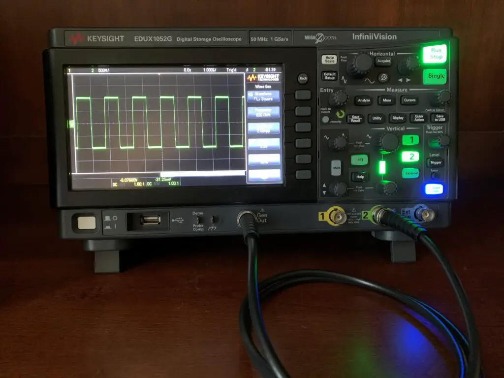
A Digital Storage Oscilloscope, also known as a DSO, is an electronic test instrument used to visualize and measure electrical signals, usually in the form of voltage over time. It works by displaying a graph of voltage on the vertical axis and time on the horizontal axis, with the amplitude and frequency of the waveform being displayed in real-time.
The Digital Oscilloscope typically has a range of input channels that can be used to measure and display multiple signals simultaneously. It also has a range of controls that allow the user to adjust the settings, such as the voltage range, timebase, and triggering, to capture and analyze the signal of interest.
Modern oscilloscopes offer more features and better accuracy than their analog counterparts, and they can also store and analyze captured waveforms using computer software.
Overall, oscilloscopes are an essential tool for electronics engineers, technicians, and hobbyists, and they are used extensively in research and development, testing and quality control, and troubleshooting and repair of electronic equipment.
How to use a Digital Storage Oscilloscope?
Here are the general steps to use an oscilloscope:
- Power on the oscilloscope: Make sure the Digital Oscilloscope is properly plugged in and powered on. Some models may have a warm-up period before use.
- Connect the probe: Connect the Digital Oscilloscope probe to the channel input. The probe typically has a ground clip that should be attached to the reference ground of the circuit or the oscilloscope’s ground lead.
- Adjust the settings: Set the desired voltage and time scales, and adjust the trigger settings. The voltage scale determines the vertical amplitude of the waveform, and the time scale determines the horizontal timebase. The trigger setting determines when the oscilloscope triggers or starts capturing the waveform.
- Connect the circuit: Connect the circuit or component being tested to the probe tip.
- View the waveform: Adjust the probe position and the trigger level, and view the waveform on the oscilloscope display.
- Analyze the waveform: Use the oscilloscope’s measurement functions to analyze the waveform, such as measuring the voltage amplitude, frequency, or time period of the signal.
- Save the waveform: Some oscilloscopes have the option to save the waveform data for further analysis or documentation.
It’s important to note that the specific steps may vary depending on the Digital Oscilloscope model and the application. It’s also essential to follow the Digital Oscilloscope and circuit manufacturer’s instructions and safety precautions to avoid damaging the equipment or causing harm to yourself.
Types of Oscilloscope probes
There are several types of oscilloscope probes available, each designed for different applications and measurement requirements. Here are some of the most common types:
- Passive probes: Passive probes are the most basic and common type of probe. They consist of a simple coaxial cable with a probe tip and a ground clip.
- Active probes: Active probes use active components, such as a high-impedance buffer amplifier or a FET input, to improve the signal quality and reduce loading effects on the circuit under test. They are suitable for high-frequency and high-impedance measurements.
- Current probes: Current probes are designed to measure the current flowing through a conductor or a circuit element without breaking the circuit. They can be either passive or active, and they typically use a Hall-effect sensor or a Rogowski coil to measure the current.
- Differential probes: Differential probes are designed to measure the voltage difference between two points in a circuit, which is useful for measuring noise or common-mode rejection in differential signals. They typically consist of two probes with an amplifier circuit that subtracts the signals.
- High-voltage probes: High-voltage probes are designed to measure high voltages, typically above 1000V, without damaging the oscilloscope or the operator. They use special insulation and voltage dividers to reduce the voltage to a safe level.
- Current-voltage probes: Current-voltage probes, also known as transducers or sensors, are designed to measure both current and voltage simultaneously, typically in power electronics applications.
The choice of probe depends on the specific application, the frequency range, the voltage level, and the required accuracy and resolution. It’s important to choose the right probe for the measurement to ensure accurate and reliable results.
Using oscilloscope to validate new designs
Oscilloscopes are an essential tool for validating new designs and circuits in electronics engineering. Here are some steps to use an oscilloscope for design validation:
- Understand the design requirements: Before using an oscilloscope to validate a new design, it’s important to understand the design requirements, such as the expected signal waveform, frequency, amplitude, and timing.
- Connect the circuit to the oscilloscope: Connect the circuit under test to the oscilloscope probe and ground clip, following the manufacturer’s instructions and safety precautions.
- Set the oscilloscope settings: Set the voltage and time scales, trigger level, and other settings to capture the signal of interest. Adjust the settings as needed to optimize the signal visibility and accuracy.
- Observe and analyze the waveform: Observe the waveform and analyze its characteristics like amplitude, frequency, rise time etc. Compare the observed waveform with the design requirements to determine whether the circuit is functioning as expected.
- Make adjustments and re-test: If the observed waveform does not meet the design requirements, make adjustments to the circuit and re-test with the oscilloscope. Continue this process until the circuit meets the design requirements.
- Document the results: Record the observed waveforms, measurements, and adjustments for documentation and future reference. This information can be useful for troubleshooting, optimization, and further development of the circuit.
Conclusion
Overall, using a Digital Oscilloscope to validate new designs is a critical step in the design and development process, as it ensures that the circuit meets the required specifications and functions as intended. With careful observation, analysis, and documentation, an oscilloscope can be a powerful tool for designing and testing new circuits.