Welcome to this comprehensive tutorial on Op Amps (Operational Amplifiers), where we will explore these powerful electronic devices. Operational amplifiers, often referred to as op amps, are widely used in various applications across different industries. They are essential components in electronic circuits, providing amplification, filtering, and signal conditioning functionalities. In this tutorial, we will dive deep into the world of op amps, discussing their applications, uses, and providing practical examples to help you master the art of working with these versatile devices.
Page Contents
Understanding Op Amps
What is an Op Amp?
An operational amplifier, commonly known as an op amp, is a type of electronic device that amplifies and processes electrical signals. It consists of a complex internal circuitry, including transistors, resistors, and capacitors, which enable it to perform various functions. Op amps are widely used in electronic circuits to amplify weak signals, perform mathematical operations, and manipulate voltage levels.
How Op Amp works?
Op amps, or operational amplifiers, are integrated circuits that amplify and manipulate electrical signals. They consist of transistors, resistors, and capacitors. Op amps have two input terminals, one for the inverting input and one for the non-inverting input, and one output terminal. They work by amplifying the voltage difference between the input terminals and producing an output voltage based on that difference. The gain of an op amp determines the amplification factor.
The Internal Structure of an Op Amp
The internal structure of an op amp consists of several key components, each playing a crucial role in its overall functionality. These components include differential input stages, gain stages, level shifters, and output stages. The differential input stages are responsible for amplifying the voltage difference between the input terminals, while the gain stages provide high voltage gain. The level shifters ensure that the output voltage remains within a specified range, and the output stage drives the load connected to the op amp.
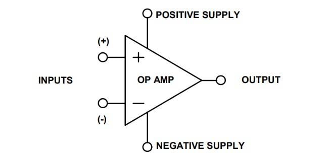
Op Amps Inputs and Outputs
Op amps typically have two input terminals and one output terminal. The inverting input (-) and the non-inverting input (+) allow external signals to be applied to the op amp. The output terminal produces a voltage that is proportional to the difference between the two input voltages. This voltage can be either positive or negative, depending on the configuration and the phase relationship between the inputs.
Modes of Operation in Op Amps
Op amps can operate in different modes, depending on how the inputs and feedback are configured. The most common modes of operation are the open-loop mode, the inverting mode, and the non-inverting mode.
- In the open-loop mode, the op amp operates without any feedback. It has a very high gain, but it is not suitable for most practical applications due to its instability and sensitivity to noise.
- In the inverting mode, the input signal is connected to the inverting terminal (-) of the op amp through a feedback resistor. The output signal is then inverted and amplified. This configuration is commonly used for signal inversion and amplification.
- In the non-inverting mode, the input signal is connected to the non-inverting terminal (+) of the op amp, while the inverting terminal is connected to the ground or a reference voltage. The output signal is amplified without inversion. This mode is often used for voltage amplification and buffering.
Op Amps Parameters
Op amps have several key parameters that define their performance characteristics. Understanding these parameters is essential for selecting the right op amp for a specific application and designing reliable circuits. Let’s take a look at some important op amp parameters:
Open-Loop Gain and Bandwidth
The open-loop gain of an op amp is the amplification factor when no feedback is applied. It is typically very high, often in the range of hundreds of thousands to millions. However, the open-loop gain is not ideal for most practical applications due to its lack of stability and sensitivity to noise. To mitigate these issues, op amps are typically used in closed-loop configurations with feedback resistors.
The bandwidth of an op amp refers to the range of frequencies over which it can provide significant amplification. It is determined by the internal circuitry and the external components connected to the op amp. The bandwidth is an important parameter to consider when working with signals of varying frequencies, as it ensures that the op amp can accurately amplify the desired frequency components.
Input and Output Impedance
The input impedance of an op amp refers to the impedance seen by the source connected to its input terminals. It is typically very high, in the order of megaohms, which means that the op amp draws minimal current from the input source. A high input impedance prevents loading of the source and ensures accurate signal transfer.
The output impedance of an op amp, on the other hand, refers to the impedance seen by the load connected to its output terminal. Ideally, the output impedance should be as low as possible to minimize signal loss and maximize power transfer to the load. However, the actual output impedance of an op amp is influenced by its internal circuitry and the external components connected to it.
Slew Rate in Op Amps
The slew rate of an op amp is a measure of how quickly it can respond to changes in the input signal. It is specified in volts per microsecond (V/µs) and determines the maximum rate at which the output voltage can change. A higher slew rate allows the op amp to accurately reproduce fast-changing signals without distortion or signal degradation.
Offset Voltage and Input Bias Current
Op amps may exhibit a small offset voltage, which is an inherent voltage that appears at the output even when the inputs are at zero voltage. The offset voltage can introduce errors in certain applications and needs to be considered for precision measurements or applications where accurate voltage levels are crucial.
Input bias current refers to the small current that flows into the input terminals of the op amp. It is important to consider the input bias current when working with high-impedance sources to ensure that the voltage drop across the input resistors is minimal.
Supply Voltage Range for Op Amps
Op amps require a power supply to operate, and the supply voltage range defines the range of voltages within which the op amp can function properly. It is important to provide a suitable power supply voltage within the specified range to ensure reliable and accurate operation of the op amp.
Noise Characteristics
Op amps can introduce noise into the circuit due to thermal effects and inherent electronic noise sources. The noise characteristics of an op amp, such as input noise voltage and input noise current, determine the level of noise that may be present in the amplified signal. It is important to consider the noise performance of an op amp, especially in applications that require high signal-to-noise ratios.
Op Amps Configurations
Op amps can be configured in various ways to suit different circuit requirements. Let’s explore some of the commonly used configurations:
Op Amp as Inverting Amplifier
The inverting amplifier is a basic op amp configuration that provides voltage amplification with signal inversion. It is formed by connecting the input signal to the inverting terminal (-) of the op amp and connecting a feedback resistor from the output terminal to the inverting terminal. The non-inverting terminal (+) is typically connected to the ground or a reference voltage.

The voltage gain of the inverting amplifier can be determined by the ratio of the feedback resistor (Rf) to the input resistor (Rin). The gain is given by the formula:
Gain = – Rf / Rin [ where Rf = R2, Rin = R1]
The negative sign indicates the inversion of the input signal. The inverting amplifier is widely used in applications such as audio amplification, signal conditioning, and waveform generation.
Op Amp as Non-Inverting Amplifier
The non-inverting amplifier is another commonly used op amp configuration that provides voltage amplification without signal inversion. In this configuration, the input signal is connected to the non-inverting terminal (+) of the op amp, and the feedback resistor is connected from the output terminal to the inverting terminal (-). The inverting terminal is usually connected to the ground or a reference voltage.

The voltage gain of the non-inverting amplifier can be calculated using the formula:
Gain = 1 + (Rf / Rin) [ where Rf = R1, Rin = R2]
The non-inverting amplifier has a positive gain, which means the output signal is in-phase with the input signal. This configuration is commonly used when signal amplification without inversion is required, such as in audio amplifiers and voltage followers.
Op Amp as Voltage Follower
The voltage follower, also known as a unity-gain amplifier or buffer, is a special configuration of an op amp where the output voltage follows the input voltage exactly. The input signal is connected directly to the non-inverting terminal (+), and the output is taken from the output terminal. The inverting terminal (-) is typically connected to the ground or a reference voltage.

The voltage follower has a gain of approximately 1, resulting in unity gain. It is mainly used to isolate the input signal from the load and provide impedance matching between stages of a circuit. The voltage follower configuration is commonly employed in audio systems, impedance matching circuits, and voltage level shifting applications.
Op Amp as Differential Amplifier
The differential amplifier is a configuration that amplifies the voltage difference between two input signals. It consists of two inputs, namely the inverting input (-) and the non-inverting input (+). The output voltage is proportional to the voltage difference between the two inputs. The differential amplifier is commonly used in applications such as instrumentation amplifiers, differential signaling, and differential voltage measurements.

The gain of a differential amplifier can be adjusted by varying the values of the feedback resistors connected to the inverting and non-inverting inputs. The differential amplifier offers excellent common-mode rejection, which means it amplifies the difference between the inputs while rejecting any common-mode noise or interference present on both inputs.
Op Amp as Integrator
The integrator configuration utilizes an op amp and a feedback capacitor to perform integration of an input signal. The input signal is connected to the inverting input (-) of the op amp through a resistor, and the feedback capacitor is connected between the output terminal and the inverting input. This configuration results in an output voltage that is proportional to the time integral of the input voltage.

The integrator configuration finds applications in circuits where integration of a signal is required, such as in analog computing, waveform generation, and frequency filters. It is important to note that an integrator has a high-pass frequency response, which means it amplifies higher frequency components while attenuating lower frequency components.
Op Amp as Differentiator
The differentiator configuration is the inverse of the integrator configuration. It uses an op amp and a feedback resistor to perform differentiation of an input signal. The input signal is connected to the inverting input (-) of the op amp through a capacitor, and the feedback resistor is connected between the inverting input and the output terminal. This configuration produces an output voltage that is proportional to the time derivative of the input voltage.

The differentiator configuration is used in applications where differentiation of a signal is necessary, such as in signal processing, frequency analysis, and pulse detection. It is important to note that a differentiator has a low-pass frequency response, which means it amplifies lower frequency components while attenuating higher frequency components.
Applications of Op Amps
Op Amp as Amplifier
One of the primary applications of operational amplifiers (op amps) is amplification. Op amps are widely used to amplify weak signals and provide gain to audio, video, and sensor signals. By adjusting the feedback network, the gain of the op amp can be set to a desired value. Amplification is essential in various systems such as audio amplifiers, communication systems, and measurement instruments.
Op Amp as Filter
Op amps are frequently employed in the design of active filters and equalizers. Filters are circuits that allow certain frequency components of a signal to pass through while attenuating others. Active filters, which use op amps as active elements, provide better performance and flexibility compared to passive filters. Op amps in combination with resistors, capacitors, and inductors can be used to design low-pass, high-pass, band-pass, and band-reject filters.
Op Amp as Equalizer
Equalizers are used to adjust the frequency response of a system to compensate for variations or to achieve a desired frequency balance. Op amps are utilized in equalizer circuits to boost or cut specific frequency bands. Equalizers find applications in audio systems, telecommunications, and radio frequency (RF) circuits.
Op Amp as Oscillator
Op amps can be used to design oscillators and waveform generators. Oscillators generate periodic waveforms at specific frequencies. Waveform generators produce waveforms of various shapes, such as sine waves, square waves, and triangle waves. Op amps, in combination with resistors, capacitors, and feedback networks, form the building blocks of oscillator and waveform generator circuits. Oscillators and waveform generators find applications in various fields. They are used in signal generation, frequency synthesis, clock circuits, audio synthesis, and modulation. Op amps play a crucial role in ensuring stable and accurate oscillation and waveform generation.
Op Amp as Schmitt Trigger
A Schmitt trigger is a specialized comparator with hysteresis. Hysteresis introduces positive feedback to the comparator, resulting in a more robust and noise-immune switching behavior. Schmitt triggers based on op amps are used in applications such as noise filtering, level detection, and signal conditioning.
Op Amp as Voltage Regulator
Op amps are utilized in voltage regulator circuits to maintain a stable output voltage regardless of changes in input voltage or load conditions. Voltage regulators based on op amps are commonly used in power supplies, battery charging circuits, and voltage-sensitive electronic devices.
Voltage regulators provide a constant output voltage by continuously adjusting the op amp’s output to compensate for changes in input voltage or load current. They ensure that the voltage supplied to critical components remains within specified limits, providing reliable and consistent operation.
Op Amp as Instrumentation Amplifier
Instrumentation amplifiers are specialized amplifiers that provide high gain, high input impedance, and excellent common-mode rejection ratio (CMRR). Op amps are often used in the design of instrumentation amplifiers for precise measurement applications.
Instrumentation amplifiers are commonly used in fields such as medical instrumentation, industrial control systems, and data acquisition. They offer superior performance in terms of accuracy, noise rejection, and signal integrity. They are also used in data acquisition systems, where precise and accurate signal conditioning is crucial. Instrumentation amplifiers provide amplification for small differential signals while rejecting common-mode noise and interference.
The high input impedance of instrumentation amplifiers ensures that they do not load the signal source, allowing for accurate measurement of low-level signals. Their high gain allows for amplification of weak signals while maintaining signal integrity and minimizing distortion.
Voltage Comparators
Voltage comparators compare the input voltages and provide an output that switches between two states based on the input voltage relationship. They are widely used in applications where the detection of voltage levels or the monitoring of thresholds is required. Voltage comparators are used in voltage detectors, window comparators, and voltage-controlled switches.
Phase Shifters
Op amps can be utilized to design phase shift circuits that shift the phase of an input signal. Phase shifters are employed in applications such as audio processing, phase-locked loops, and communications systems.
Phase shifters introduce a controlled phase shift to the input signal, allowing for various signal processing techniques. Op amps, in combination with resistors, capacitors, and inductors, can be used to create phase shift networks with specific phase shift characteristics. Phase shifters are used in audio equalizers, frequency modulation (FM) circuits, and radio frequency (RF) filters.
Logarithmic Amplifiers
Op amps can be configured as logarithmic amplifiers to provide an output voltage proportional to the logarithm of the input voltage. Logarithmic amplifiers are used to compress wide dynamic ranges of signals into a more manageable range. They find applications in audio processing, where they are used to compress the dynamic range of audio signals and improve the overall audio quality. Logarithmic amplifiers are also used in RF signal processing and radar systems.
Voltage-to-Frequency Converters
Op amps can be used to design voltage-to-frequency converters that convert an analog voltage input into a corresponding frequency output. Voltage-to-frequency converters generate a frequency output that is proportional to the input voltage. This frequency output can be easily measured and processed by digital circuits or microcontrollers. Voltage-to-frequency converters are used in frequency counters, digital voltmeters, and digital frequency synthesizers.
Sample-and-Hold Circuits
Op amps are employed in sample-and-hold circuits to capture and hold an input voltage at a specific instant in time. Sample-and-hold circuits find applications in analog-to-digital conversion, data acquisition systems, and communication systems.
Sample-and-hold circuits consist of a switch and a capacitor controlled by an op amp. The op amp holds the input voltage on the capacitor when the switch is closed and maintains the held voltage when the switch is opened. This allows for accurate sampling and subsequent processing of analog signals.
Current Sources and Sinks
Op amps can be used to generate precise current sources or sinks. Current sources and sinks are employed in various applications, including biasing circuits, sensor excitation, and constant current loads.
Op amps can be configured in a feedback configuration to generate a stable and precise current. These current sources or sinks are used to provide a constant current to a load resistor, sensor, or other components. They ensure a consistent and controlled flow of current, which is essential in many electronic systems.
Current sources find applications in circuits where a stable and accurate current is required, such as in temperature sensors, light sensors, and biasing circuits for transistors. Current sinks, on the other hand, are used to create a controlled load for testing and measurement purposes.
Waveform Shaping and Generation
Op amps are versatile tools for waveform shaping and generation. They can be used to create a variety of waveforms with different shapes and characteristics, including sine waves, square waves, triangle waves, and pulse waves.
By combining op amps with resistors, capacitors, and feedback networks, engineers can design circuits that generate precise and well-defined waveforms. These waveforms are used in various applications such as audio synthesis, modulation, frequency synthesis, and waveform testing.
Op amps are also used in waveform shaping circuits to modify the characteristics of existing waveforms. By applying filters, amplifiers, and other signal conditioning techniques, op amps can shape waveforms to meet specific requirements, such as removing noise, adjusting amplitudes, or adding frequency components.
Voltage-to-Current Conversion
Op amps can be utilized to convert a voltage input into a corresponding current output. This voltage-to-current conversion is achieved by using the op amp in a transconductance configuration.
In voltage-to-current conversion circuits, the input voltage is applied to the non-inverting terminal of the op amp, while the inverting terminal is grounded or connected to a reference voltage. The output current is then generated based on the input voltage and the feedback resistor connected between the op amp’s output and the inverting terminal.
Voltage-to-current conversion is essential in applications such as current loop interfaces, current-controlled systems, and analog signal transmission. It allows for the conversion of voltage signals into current signals, which are less susceptible to noise and can be transmitted over long distances without significant degradation.
Voltage Controlled Oscillators
Op amps can be used to design voltage-controlled oscillators (VCOs). VCOs are oscillators whose frequency can be controlled by an input voltage.
In voltage-controlled oscillator circuits, op amps are used to generate a control voltage that determines the oscillation frequency. By adjusting the control voltage, the output frequency of the VCO can be varied over a wide range. VCOs find applications in frequency modulation (FM) systems, phase-locked loops, and frequency synthesis.
Op amps provide the amplification and feedback necessary for stable and accurate oscillation. By combining op amps with capacitors, resistors, and other components, engineers can create VCO circuits with precise frequency control and excellent frequency stability.
Voltage-to-Phase Conversion
Op amps can be employed to convert a voltage input into a corresponding phase shift output. Voltage-to-phase converters are used in applications such as phase modulation, phase detection, and phase-locked loops.
In voltage-to-phase conversion circuits, the input voltage is applied to the non-inverting terminal of the op amp, while the inverting terminal is connected to a reference voltage or ground. The phase shift is determined by the input voltage and the feedback components connected to the op amp.
Voltage-to-phase converters find applications in communication systems, audio processing, and frequency modulation. They allow for precise control of phase shift, which is crucial in various modulation and signal processing techniques.
Analog-to-Digital and Digital-to-Analog Conversion
Op amps play a crucial role in analog-to-digital (ADC) and digital-to-analog (DAC) conversion circuits. They are used in sample-and-hold circuits, voltage references, and analog signal conditioning stages to ensure accurate and reliable conversion between analog and digital domains.
Signal Conditioning
Op amps are also used for signal conditioning purposes. Signal conditioning involves modifying the characteristics of a signal to make it suitable for further processing or measurement. Op amps can be used to filter out unwanted noise, remove DC offsets, adjust signal levels, and convert signals from one form to another. Signal conditioning circuits based on op amps are commonly used in sensors, transducers, and data acquisition systems.
Active Filters
Op amps can be utilized to design active filter circuits that provide precise frequency response characteristics. Active filters offer advantages over passive filters, including flexibility, adjustable parameters, and better performance. Active filters find applications in audio systems, telecommunications, and signal processing.
Active Rectifiers
Op amps can be utilized as active rectifiers to convert alternating current (AC) signals into direct current (DC) signals. Active rectifiers find applications in power supplies, audio signal processing, and motor control.
Peak Detectors

Op amps can be employed as peak detectors to capture and hold the peak value of an input signal. Peak detectors find applications in amplitude measurement, envelope detection, and peak voltage monitoring.
Voltage Multipliers
Op amps can be used to design voltage multiplier circuits that generate higher voltage outputs from lower voltage inputs. Voltage multipliers find applications in power supplies, electronic ballasts, and high-voltage generation.
Op Amps Specifications
When selecting an operational amplifier (op amp) for your circuit, it is essential to understand and evaluate its specifications. Here are some key op amp specifications to consider:
- Gain: The gain of an op amp specifies the amplification it provides to the input signal. It is typically expressed as the open-loop voltage gain (e.g., 100,000) or in decibels (e.g., 100 dB). The gain determines how much the op amp amplifies the input signal, and it can be adjusted using external feedback components.
- Bandwidth: The bandwidth of an op amp represents the range of frequencies over which it can provide the specified gain. It is usually specified as the frequency at which the gain drops by a certain value (e.g., -3 dB). The bandwidth determines the maximum frequency at which the op amp can accurately amplify the input signal.
- Input and Output Voltage Range: The input and output voltage ranges indicate the minimum and maximum voltages that the op amp can handle without distortion or clipping. It is important to select an op amp with input and output voltage ranges that are compatible with the signal levels in your circuit.
- Input and Output Impedance: The input impedance refers to the resistance seen by the signal source connected to the op amp’s input. The higher the input impedance, the less the op amp loads the source, allowing for accurate signal transfer. The output impedance represents the resistance the op amp presents to the load. A lower output impedance ensures efficient signal delivery.
- Slew Rate: The slew rate indicates how quickly the output voltage of the op amp can change in response to a step input. It is measured in volts per microsecond (V/µs) and determines the op amp’s ability to accurately reproduce fast-changing signals without distortion.
- Noise Characteristics: Op amps have inherent noise that can affect the signal quality. Two important noise specifications are input voltage noise (expressed in nV/√Hz) and input current noise (expressed in pA/√Hz). Lower values indicate lower noise levels, resulting in cleaner signals.
- Supply Voltage Range: The supply voltage range specifies the minimum and maximum voltages required to power the op amp. It is crucial to select an op amp that can operate within the available power supply range of your circuit.
- Common-Mode Rejection Ratio (CMRR): CMRR measures an op amp’s ability to reject common-mode signals that are present on both input terminals. It is expressed in decibels (dB), and a higher value indicates better rejection of common-mode noise.
- Offset Voltage: The offset voltage represents the small voltage difference between the op amp’s input terminals when the input voltage is zero. It can cause an output offset or error in the amplified signal. Lower offset voltages are desirable for accurate signal amplification.
- Temperature Range: The temperature range specifies the operating temperatures at which the op amp can maintain its specified performance. It is important to select an op amp suitable for the temperature conditions in your application.
These specifications, along with others specific to certain op amps, help in determining the most suitable op amp for your circuit design. Understanding these specifications allows you to make informed decisions and ensure that the chosen op amp meets your circuit’s requirements.
Single-Supply vs. Dual-Supply Operation
Operational amplifiers (op amps) can be operated using either a single power supply or dual power supplies. The choice between single-supply and dual-supply operation depends on the specific requirements and constraints of your circuit. Here are some considerations for each:
Single-Supply Operation:
- Simplicity: Single-supply operation simplifies the power supply setup by using only one power source.
- Cost and Space: Using a single power supply reduces the cost and space requirements of the circuit since only one power source is needed.
- Compatibility: Single-supply operation is suitable for applications where the input and output signals are referenced to a single ground or a specific voltage level.
- Ease of Integration: Single-supply op amps are commonly available and widely used, making them easier to integrate into circuit designs.
- Battery-Powered Applications: Single-supply operation is often preferred in battery-powered applications where a single voltage source is available.
Dual-Supply Operation:
- Extended Signal Range: Dual-supply operation allows for a wider input and output signal range since both positive and negative supply voltages are available.
- Symmetric Signal Handling: Dual-supply operation enables symmetrical handling of signals, which is important for applications that involve both positive and negative signal swings.
- Improved Signal Fidelity: With dual supplies, op amps can offer better linearity, reduced distortion, and improved signal fidelity compared to single-supply configurations.
- Voltage Biasing: Dual-supply operation facilitates voltage biasing and referencing of input and output signals to specific levels, which is useful in certain applications.
- AC-Coupled Signals: Dual-supply operation is commonly used when dealing with AC-coupled signals or when bidirectional signal paths are required.
When deciding between single-supply and dual-supply operation, consider the nature of your signals, the required voltage range, the need for symmetric signal handling, and the overall system requirements. It’s important to carefully evaluate the advantages and limitations of each approach to ensure the best match for your specific application.
Stability and Compensation in Op Amps
Maintaining stability in operational amplifier (op amp) circuits is crucial for reliable and accurate operation. Here are some considerations for achieving stability and compensation in op amp circuits:
- Feedback Stability: Op amps are typically used in closed-loop configurations with feedback resistors and capacitors. Ensuring proper stability requires careful selection and design of the feedback network. Using appropriate resistor and capacitor values in the feedback loop can help optimize stability.
- Phase Margin: Phase margin measures the difference between the phase shift of the op amp and a 180-degree phase shift. It indicates the stability margin of the circuit. A phase margin of at least 45 degrees is generally recommended for stability. If the phase margin is too low, the circuit can become prone to oscillation.
- Compensation Capacitors: Some op amps require external compensation capacitors to stabilize their operation. These capacitors are connected between specific pins of the op amp to improve stability. The datasheet of the op amp should provide guidance on the required compensation capacitor values and placement.
- Unity-Gain Stability: Some op amps may exhibit stability issues when operated at unity gain (gain of 1). To ensure stability in unity-gain configurations, select op amps that are specifically designed for unity-gain stability or use compensation techniques such as adding a small resistor in series with the feedback capacitor.
- Load Capacitance: The capacitive load connected to the output of the op amp can affect stability. Large capacitive loads can introduce phase shifts and reduce stability. Consider the capacitive load requirements of your circuit and ensure that the op amp is stable with the specified load capacitance.
- Bypassing and Decoupling: Proper power supply bypassing and decoupling techniques are important for stability. Use bypass capacitors to filter out high-frequency noise and decouple the power supply from the op amp to prevent unwanted oscillations and instability.
- Printed Circuit Board (PCB) Layout: A well-designed PCB layout is essential for stability. Minimize the lengths of high-impedance traces, provide proper ground planes, and pay attention to signal routing to avoid noise coupling and unwanted feedback paths that can lead to instability. Follow best practices for grounding, minimize loop area, and keep sensitive traces away from noise sources.
- Simulation and Analysis: Utilize circuit simulation software to analyze the stability of your op amp circuit. Perform stability analysis by simulating the frequency response, gain margin, and phase margin to identify any potential stability issues. Adjust component values or modify the compensation network if needed to improve stability.
- Temperature Effects: Temperature variations can affect the stability of op amp circuits. Consider the temperature range of your application and ensure that the selected op amp is stable and maintains its performance across the specified temperature range.
- Feedback Network Compensation: In certain cases, additional compensation techniques may be required to improve stability. These techniques include adding pole-zero compensation networks, adjusting component values, or using specialized stability-enhancement techniques available in some op amps.
It is important to thoroughly understand the stability requirements of your op amp circuit and carefully analyze its behavior to ensure stability. By considering factors such as feedback stability, phase margin, compensation capacitors, load capacitance, bypassing and decoupling, PCB layout, simulation, temperature effects, and feedback network compensation, you can design stable op amp circuits that operate reliably and accurately.
Power Supply Decoupling of Op Amps
Decoupling is an essential technique in operational amplifier (op amp) circuits to minimize noise, stabilize the power supply, and ensure reliable operation. Here are some considerations for effective power supply decoupling:
- Bypass Capacitors: Place bypass capacitors close to the power supply pins of the op amp. Bypass capacitors provide a low-impedance path for high-frequency noise and transient currents, effectively filtering out noise and stabilizing the power supply. Ceramic capacitors with values in the range of 100 nF to 1 µF are commonly used for bypassing.
- Decoupling Capacitors: Besides bypass capacitors, additional decoupling capacitors can be placed strategically on the power supply lines of the op amp. These capacitors help attenuate high-frequency noise and provide local energy storage, preventing voltage drops and fluctuations in the power supply caused by dynamic load variations.
- Capacitor Placement: Ensure that bypass and decoupling capacitors are placed as close as possible to the op amp’s power supply pins to minimize the length of the power supply traces and reduce inductance. Shorter traces and lower inductance help improve the effectiveness of the decoupling capacitors.
- Capacitor Types: Choose capacitor types suitable for decoupling purposes. Ceramic capacitors are commonly used for their low equivalent series resistance (ESR) and high self-resonant frequency, making them effective in decoupling high-frequency noise. Electrolytic capacitors can also be used for decoupling larger voltage fluctuations and low-frequency noise.
- Value Selection: Select decoupling capacitor values based on the frequency range of the noise to be decoupled. Higher capacitance values are more effective at lower frequencies, while smaller capacitance values are better for higher frequencies. Consider the op amp’s datasheet for recommended decoupling capacitor values.
- Power Supply Traces: Design power supply traces with sufficient width to minimize resistance and inductance. Wider traces help reduce voltage drops and prevent power supply-induced noise. Avoid routing power supply traces near high-frequency noise sources or signal traces to minimize coupling.
- Grounding: Proper grounding is crucial for effective power supply decoupling. Create a dedicated ground plane for the op amp circuit to minimize ground impedance and prevent ground loops. Ensure a low-impedance ground connection for both the op amp and the decoupling capacitors.
- Multilayer PCBs: If possible, use multilayer PCBs for your op amp circuits. Multilayer PCBs offer several advantages over single-layer or double-layer PCBs. They consist of multiple layers of conductive traces and insulating material sandwiched together, allowing for increased routing density and better signal isolation.
- Shielding and Filtering: In noise-sensitive applications, consider using shielding techniques to protect the op amp circuit from external electromagnetic interference. Additionally, adding passive filters, such as ferrite beads or inductors, in the power supply lines can further reduce high-frequency noise and improve decoupling.
- Testing and Verification: After implementing power supply decoupling in your op amp circuit, perform thorough testing and verification to ensure the effectiveness of the decoupling technique. Measure the power supply noise levels, check for stability, and verify the overall performance of the circuit under various operating conditions.
By following these guidelines for power supply decoupling, you can minimize power supply-induced noise, stabilize the power rails, and enhance the performance and reliability of your op amp circuit.
PCB Layout Considerations for Op Amps
The layout of the printed circuit board (PCB) plays a crucial role in ensuring the optimal performance of operational amplifier (op amp) circuits. Here are some important considerations for PCB layout when working with op amps:
- Ground Plane: Create a dedicated ground plane that provides a low-impedance reference for the op amp circuit. The ground plane should be connected to the system ground and cover a significant portion of the PCB. It helps minimize noise, reduce ground loops, and provide a stable reference for the op amp’s inputs and outputs.
- Component Placement: Place the op amp as close as possible to the components it interacts with, such as resistors, capacitors, and feedback elements. Minimize trace lengths to reduce parasitic effects and noise pickup. Pay attention to the orientation and placement of components to ensure signal integrity and minimize signal coupling.
- Trace Routing: Keep signal traces as short as possible to minimize stray capacitance and inductance. Route sensitive analog signals away from noisy digital or high-power traces to prevent coupling and interference. Use wider traces for power and ground connections to minimize resistance and voltage drops.
- Separation of Analog and Digital Signals: If your PCB includes both analog and digital circuitry, separate the analog and digital signal paths to avoid cross-talk and interference. Place a physical barrier or keep sufficient distance between the analog and digital sections. Use separate ground planes for analog and digital sections if possible.
- Decoupling Capacitor Placement: Position decoupling capacitors close to the power supply pins of the op amp, as discussed in the section on power supply decoupling. Place them as physically close as possible and connect them directly to the power and ground planes to minimize trace lengths and inductance.
- Thermal Considerations: Op amps can generate heat during operation. Ensure adequate thermal dissipation by providing thermal vias or heat sinks if necessary. Avoid placing heat-sensitive components or traces near the op amp to prevent thermal interference.
- Signal Integrity: Minimize the risk of noise coupling and signal degradation by using proper impedance matching techniques for high-speed signals. Maintain controlled impedance for transmission lines and use appropriate termination methods, such as series resistors or termination resistors, to prevent signal reflections and ensure clean signal transmission.
- Test Points: Incorporate test points at strategic locations in the PCB layout to facilitate circuit testing, debugging, and future modifications. Test points can include access points for probing critical signals, voltage measurement points, and component test points.
- Noise Mitigation: Implement good grounding techniques, such as star grounding, to minimize noise pickup and ground loops. Use proper shielding techniques for sensitive analog signals. Add filtering components, such as ferrite beads or low-pass filters, to suppress noise and improve signal quality.
- Manufacturability and Serviceability: Consider the manufacturability and serviceability aspects of your PCB layout. Ensure proper clearances, trace widths, and component placement to meet manufacturing requirements. Provide component designators, polarity markings, and clear silkscreen labels to aid in assembly and troubleshooting. Consider accessibility and ease of replacing components, if needed, during servicing.
- Electromagnetic Compatibility (EMC): Follow EMC guidelines to minimize electromagnetic interference (EMI) and ensure compliance with regulations. Keep sensitive analog traces away from high-speed digital signals, use proper ground and power planes, and implement shielding techniques as necessary. Test the PCB for EMC compliance and make adjustments if required.
- Documentation: Maintain comprehensive documentation of the PCB layout, including schematic diagrams, component placement information, and routing guidelines. Document any special considerations, such as high-frequency signal routing, impedance matching, or thermal management techniques. Well-documented PCB layouts help with future modifications, troubleshooting, and collaboration with other stakeholders.
- Iterative Design and Testing: PCB layout is often an iterative process involving prototyping, testing, and refinement. Perform thorough testing and verification of the PCB layout to ensure the desired performance of the op amp circuit. Analyze signal integrity, noise levels, stability, and other relevant parameters, and make adjustments as necessary to achieve optimal results.
By incorporating these PCB layout considerations, you can minimize noise, ensure signal integrity, optimize thermal performance, and improve the overall reliability and performance of your op amp circuit. Careful attention to layout details and adherence to best practices will help you achieve the desired functionality and meet the specific requirements of your application.
Practical Examples of Op Amps
Designing an Audio Amplifier
One common application of operational amplifiers (op amps) is in audio amplifier circuits. By carefully selecting the appropriate op amp and designing the supporting circuitry, you can create an audio amplifier that amplifies low-level audio signals from sources such as microphones or audio players. The amplified signal can then be sent to a speaker or headphones for audio playback.
Low-Pass Filter Design
Op amps are commonly used in the design of low-pass filters, which allow low-frequency signals to pass through while attenuating higher-frequency components. Low-pass filters are used in various applications, including audio processing, signal conditioning, and anti-aliasing in analog-to-digital converters (ADCs). By selecting the appropriate op amp and designing the filter circuitry, you can achieve the desired cutoff frequency and filter characteristics.
Temperature Sensor Interface
Op amps can be used to interface temperature sensors, such as thermocouples or resistance temperature detectors (RTDs), with microcontrollers or data acquisition systems. The op amp circuit can amplify and condition the small voltage or current signals produced by the temperature sensor, making them suitable for measurement and further processing.
Light Sensor Circuit
Op amps are also useful in light sensor circuits, which convert variations in light intensity into electrical signals. By connecting a light-dependent resistor (LDR) or a photodiode to an op amp, you can create a light sensor circuit that converts light changes into voltage variations. This can be used for applications such as automatic lighting control, optical detection, or solar energy harvesting.
Precision Voltage Reference
Op amps can be employed to create precision voltage references, which are crucial in many electronic systems. By using a stable voltage reference, such as a zener diode or a precision voltage reference IC, in combination with an op amp, you can generate a precise and stable voltage output. Precision voltage references are commonly used in analog-to-digital converters, instrumentation circuits, and voltage regulators.
Strain Gauge Amplifier
Strain gauges are widely used in applications that involve measuring mechanical strain, such as force or pressure. Op amps can be utilized to amplify the small variations in resistance produced by the strain gauge, allowing for accurate measurement of the applied strain. Strain gauge amplifiers are employed in areas like structural monitoring, load cells, and industrial automation.
Conclusion
Operational amplifiers are versatile and indispensable components in modern electronic circuits. They provide amplification, signal conditioning, filtering, and mathematical operations that are essential for various applications. By understanding the different configurations, parameters, and applications of op amps, engineers and hobbyists can effectively design and implement circuits that meet their specific requirements. Mastering op amps opens up a world of possibilities in electronic design and empowers engineers to create innovative solutions across a wide range of industries and fields.
FAQs
Q. What is the ideal voltage gain of an op amp?
A. The ideal voltage gain of an op amp is theoretically infinite. In an ideal op amp, the voltage gain is determined by the external resistors and feedback configuration used in the circuit. However, in practical op amps, the voltage gain is typically very high, often in the range of tens of thousands or more.
Q. Can I use op amps with single-supply voltage?
A. Yes, op amps can be used with single-supply voltage configurations. Single-supply op amp circuits are commonly used in applications where a dual-supply voltage is not available or practical. When using a single-supply voltage, proper biasing and biasing techniques need to be employed to ensure the op amp operates within its specified voltage range.
Q. How do I calculate the gain of an inverting amplifier?
A. The gain of an inverting amplifier can be calculated using the formula: Gain = -Rf/Rin, where Rf is the feedback resistor and Rin is the input resistor. By choosing appropriate values for these resistors, the desired gain can be achieved. It’s important to consider the input and output impedance requirements of the op amp and the desired overall circuit performance.
Q. What is the purpose of feedback in op amp circuits?
A. Feedback in op amp circuits serves several purposes. It helps control the gain and stability of the op amp, reduces distortion, and improves linearity. By connecting a portion of the output signal back to the input, the op amp’s characteristics can be controlled and tailored to meet the specific requirements of the application.
Q. Are op amps suitable for high-frequency applications?
A. Op amps can be suitable for high-frequency applications, but it depends on the specific op amp’s bandwidth and slew rate. Higher-speed op amps with wide bandwidths and fast slew rates are designed for high-frequency applications. It’s important to select an op amp that meets the frequency requirements of the application and consider other factors like stability and noise performance.
Q. How can I minimize noise in my op amp circuit?
A. To minimize noise in an op amp circuit, several techniques can be employed. These include selecting low-noise op amps, properly bypassing power supplies, using shielding techniques, minimizing the length of high-impedance traces, and employing proper grounding practices. It’s also important to consider the noise contributions from external components and the PCB layout.
Q. What is the main advantage of using op amps in electronic circuits?
A. Operational amplifiers offer high gain, versatility, and stability, making them suitable for a wide range of applications. They can amplify weak signals, perform mathematical operations, and provide precision signal conditioning.
Q. Can I use an operational amplifier as a voltage source?
A. Operational amplifiers are not designed to be used as standalone voltage sources. They require a power supply to operate and are typically used as active components in electronic circuits to amplify, filter, or process signals.
Q. What is the difference between an inverting and a non-inverting amplifier?
A. In an inverting amplifier, the input signal is connected to the inverting terminal (-) of the op amp, and the output signal is an inverted (180-degree phase shift) and amplified version of the input signal. In a non-inverting amplifier, the input signal is connected to the non-inverting terminal (+), and the output signal is in-phase with the input signal.
Q. What are some common op amp package types?
A. Op amps are available in various package types, including dual in-line package (DIP), small outline integrated circuit (SOIC), quad flat package (QFP), and surface mount technology (SMT) packages. The choice of package depends on the specific application and circuit board requirements.
Q. Can I directly connect an op amp to a microcontroller or digital circuit?
A. Op amps are analog devices, and if you want to interface them with digital circuits or microcontrollers, you may need additional components such as level shifters, analog-to-digital converters (ADCs), or digital-to-analog converters (DACs) depending on the specific requirements of the application.
Q. Who are some common op amps manufacturers?
A. Some well-known op amp manufacturers include Texas Instruments, Analog Devices, Maxim Integrated, STMicroelectronics, and Linear Technology (now part of Analog Devices). These manufacturers offer a wide range of op amps with various specifications and features.